Wednesday 31 July 2019

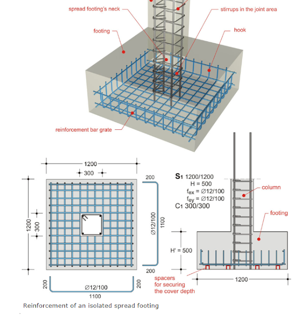
EXAMPLE 7.7.2. ESTIMATING ISOLATED FOOTING REINFORCEMENT OF A SMALL STRUCTURE

Estimate the rebars and the tie wire for 8 footings specified as shown.
credits to BuildingHow.com

From the plans, we can count the number of rebars used (D12mm). For isolated footing, bars are usually placed both ways, hence, the number of bars laid horizontally is the same number laid vertically. For the length of the bars, specification already shows the clear length and hooks' length.


Thus:  


Commercial lengths can be exactly divided by 1.50, so it's the estimator's discretion on which commercial length the rebars be converted.


#16 GI Tie Wire:


D12mm rebars can be tied using 25cm wire.


Back to 7.0. Estimating Concrete Reinforcement
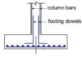
EXAMPLE 7.7.1. ESTIMATING ISOLATED FOOTING REINFORCEMENT

Estimate the reinforcement required for the 1.50m square footing shown. Reinforcement used is D12mm steel bars. Determine the tie wire needed.

credits to The Constructor


The configuration of the rebars is shown from the plan. There is no need for any hook or bend on the rebars. This means that the length of the bars only includes the size of the column less the clear cover.


From plans, number of bars can be determined. (Specification is usually the number of bars used both ways, or the spacing between bars)


Thus, rebars required:

                24pcs D12mm RSB at 1.35m

It is the estimator's discretion on which commercial length these bars are to be taken from. Note the remaining length if they can still be used in the construction for other purposes.


#16 GI Tie Wire:


Back to 7.0. Estimating Concrete Reinforcement

Tuesday 30 July 2019

EXAMPLE 7.6.1. ESTIMATING TIE WIRE FOR CHB REINFORCEMENT

From the previous example of a 4.0m x 3.0m wall, estimate the tie wire required in kilograms.

From the previous example: 

      Vertical reinforcement spacing: 80cm
      Horizontal reinforcement spacing: at every 3 layers


Tie wire estimation can be done in two ways:

a. Direct count. identify the number of intersections created with the vertical and horizontal reinforcements.

   From previous results: 5 horizontal layers of 4m
                                     5 vertical layers of 3m


Because CHB reinforcement only uses D10mm rebars, the applicable length of tie wire needed is 25cm.


b. Block method. Using a table, determine the weight of tie wire needed.


   Use the table with 25cm tie wire:


Back to 7.0. Estimating Concrete Reinforcement
Monday 29 July 2019

EXAMPLE 7.5.1. ESTIMATING CHB WALL REINFORCEMENT

Determine the 10mm vertical and horizontal reinforcement fr the CHB wall 4.0m length and 3.0m high. Reinforcement is spaced at 80cm on centers vertically and every three layers respectively.


a. Direct counting:

For horizontal reinforcement: Horizontal reinforcement is every three layers of CHB height as 0.20m, thus total height of each layer is 0.60m.


So, for horizontal reinforcement: 5 layers of 4.00m D10mm rebars.

For vertical reinforcement:


So, for vertical reinforcement: 5 layers of 3.00 D10 rebars.


To convert the needed steel bars in commercial sizes, the least wastage is by using 7.5m lengths cut into 4m and 3m (wastage: 0.50m each bar).

So, use:     5pcs D10mm x 7.50m RSB


b. Square Meter Method or Area Method:


For vertical reinforcement, using the table:


SPACINGLENGTH OF BARSLENGTH OF BARS

PER BLOCK
PER SQ.M.
cm.
m.
m.


40
0.235
2.930
60
0.171
2.130
80
0.128
1.600


Convert into commercial lengths:  4pcs D10mm x 5.00m

For horizontal reinforcement, using the table:


SPACING
LENGTH OF BARS
LENGTH OF BARS
LAYERS
PER BLOCK
PER SQ.M.

m.
m.


2
0.264
3.30
3
0.172
2.15
4
0.138
1.72


This can be converted to:      4pcs D10mm x 5.00m
                                           1pc  D10mm x 6.00m


In summary, order:               8pcs D10mm x 5.00m RSB
                                           1pc  D10mm x 6.00m  RSB

c. Unit Block Method. This method requires the number of CHB.


From the table above:

Vertical reinforcement:


Convert into commercial lengths:  4pcs D10mm x 5.00m

Horizontal reinforcement:


This can be converted to:      4pcs D10mm x 5.00m
                                           1pc  D10mm x 6.00m


In summary, order:               8pcs D10mm x 5.00m RSB

                                           1pc  D10mm x 6.00m  RSB

Note: The results of the two last methods yield the total number of bars needed. The estimator would have no means of knowing the lengths of bars to be installed vertically and horizontally. Bar scheduling with these methods would be hard to identify.


Back to 7.0. Estimating Concrete Reinforcement
EXAMPLE 7.2.1. DETERMINING SPLICE LENGTHS

Determine the length of the splice joint for a 16mm steel bars if they are used as:
   a. Tensile reinforcement of a beam
   b. Compressive reinforcement of a beam


a. Used as tensile reinforcement:


b. Used as a compressive reinforcement:


Back to 7.0. Estimating Concrete Reinforcement
EXAMPLE 6.1.3. ESTIMATING STRINGERS

Determine the length of an open wood stringer with the following data: run distance = 3.50m and height of the rise =2.50m.

Using the Pythagorean Theorem:


Assuming 18cm riser, calculate the number of steps:


Use the table for determination of rise and tread:


NO OF STEPSLENGTH OF STRINGERLENGTH OFRUNHEIGHT OF RISE

TREAD
TREAD
TREAD
TREAD
RISER
RISER

WIDTH
WIDTH
WIDTH
WIDTH
HEIGHT
HEIGHT

25cm
30cm
25cm
30cm
17cm
18cm


4
1.05
1.23
0.80
1.00
0.68
0.72
5
1.31
1.54
1.00
1.25
0.85
0.90
6
1.57
1.85
1.20
1.50
1.02
1.08
7
1.84
2.16
1.40
1.75
1.19
1.26
8
2.10
2.47
1.60
2.00
1.36
1.44
9
2.36
2.78
1.80
2.25
1.53
1.62
10
2.62
3.08
2.00
2.50
1.70
1.80
11
2.89
3.39
2.20
2.75
1.87
1.98
12
3.15
3.70
2.40
3.00
2.04
2.16
13
3.41
4.00
2.60
3.25
2.21
2.34
14
3.67
4.31
2.80
3.50
2.38
2.52
15
3.94
4.62
3.00
3.75
2.55
2.70
16
4.20
4.93
3.20
4.00
2.72
2.88
17
4.46
5.24
3.40
4.25
2.89
3.06
18
4.73
5.55
3.60
4.50
3.06
3.24
19
5.00
5.85
3.80
4.75
3.23
3.42
20
5.62
6.16
4.00
5.00
3.40
3.60


Identify 14 steps yields 4.31 stringer length by 30cm tread width; the run at 30cm = 3.50 and the height of rise at 18cm = 2.52.


EXAMPLE 6.1.2. ESTIMATING A STAIRCASE II

Determine the height of the riser and the width of the tread when the rise is 2.65m and the run is 2.75m.


Assuming rise height of 18cm, compute the number of steps for the total rise of 2.65m.


Re-check the height of each riser:


Assuming a run of 30cm, compute the total run of the stairs:


Have another trial of tread width = 25cm:


Thus:  15 steps of 0.177m rise and 20cm tread


Back to 6.0. Estimating Staircases

EXAMPLE 6.1.1. ESTIMATING A STAIRCASE

Determine the number of steps and the height of the riser if the total height of the rise is 2.20m using a 30 cm. width of the tread.

Assuming 17cm height of rise, compute for the number of steps to reach the upper level:


Re-check the height of the riser:


Determine the distance of the run:


   where:


Back to 6.0. Estimating Staircases

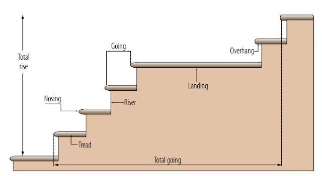
6.0. ESTIMATING STAIRCASES

Constructing a staircase is like erecting an inclined bridge between points of different floors with treads and risers.

credits to Multiturn.co.uk

6.1. LAYING OUT STAIRS


Enumerated below are the fundamental procedures for stairs layout.

  1. Determine the height of the riser. This would usually be computed from the total clear height of each floor divided by the desired number of steps. A normal riser height is from 17 to 18cm for comfortable ascending and descending. However, the maximum riser height is 20cm.
  2. The run distance can be computed from the number of steps computed using the desired riser height. Determine the tread width and solve for the total run distance. The effective tread width would be 2 inches (50mm) less the tread width. This reduction is due to the nosing.


credits to UX Stack Exchange


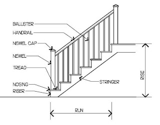
6.2. PARTS OF A STAIRCASE


credits to Pinterest


6.3. STRINGER


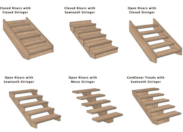
The inclined plane which supports the tread and the riser of a stair is called stringer. A stringer's length is determined by using trigonometry with Pythagorean Theorem or by actual measurements using tape or measuring devices.

Stringers are classified according to the methods of attaching risers and tread.

  • Cut-type stringers, which are used in modern stair designs.
  • Cleated type stringers, which are used for very rough work.
  • Built-up type stringer, used on wide stairs which need center stringer.
  • Rabbeted type stringer, used for fine work and usually made at the mill. The risers and treads are held in the rabbets using wedges which are set in with glue.


credits to Pinterest

NO OF STEPSLENGTH OF STRINGERLENGTH OFRUNHEIGHT OF RISE

TREAD
TREAD
TREAD
TREAD
RISER
RISER

WIDTH
WIDTH
WIDTH
WIDTH
HEIGHT
HEIGHT

25cm
30cm
25cm
30cm
17cm
18cm


4
1.05
1.23
0.80
1.00
0.68
0.72
5
1.31
1.54
1.00
1.25
0.85
0.90
6
1.57
1.85
1.20
1.50
1.02
1.08
7
1.84
2.16
1.40
1.75
1.19
1.26
8
2.10
2.47
1.60
2.00
1.36
1.44
9
2.36
2.78
1.80
2.25
1.53
1.62
10
2.62
3.08
2.00
2.50
1.70
1.80
11
2.89
3.39
2.20
2.75
1.87
1.98
12
3.15
3.70
2.40
3.00
2.04
2.16
13
3.41
4.00
2.60
3.25
2.21
2.34
14
3.67
4.31
2.80
3.50
2.38
2.52
15
3.94
4.62
3.00
3.75
2.55
2.70
16
4.20
4.93
3.20
4.00
2.72
2.88
17
4.46
5.24
3.40
4.25
2.89
3.06
18
4.73
5.55
3.60
4.50
3.06
3.24
19
5.00
5.85
3.80
4.75
3.23
3.42
20
5.62
6.16
4.00
5.00
3.40
3.60


6.4. NATIONAL BUILDING CODE ON STAIRS

  1. The minimum width of any stair slab and the minimum diameter-dimension of any landing should be at least 110 centimeters.
  2. The maximum rise of stairs step should be between 17 and 19 centimeters.  A rise less than 16 cm nor more than 19 cm is not considered as ideal stair.
  3. The minimum width of a tread exclusive of the nosing shall be 25 centimeters.
  4. The maximum height of a straight flight between landing is generally 3.60meters except those serving as exit from places of assembly where a maximum height of 2.40 meters is normally specified.
  5. The number of stairway in a building depends upon the number of probable occupants per floor, the width of stairway and the building floor area. The distance from any point in an open floor area to the nearest stairway shall not exceed 30 meters and that the corresponding distance along corridors in a particular area shall not exceed 38 meters.
  6. The combined width of all the stairway in any floor shall accommodate at one time the total number of persons occupying the largest floor area under the condition that one person for each 0.33 sq.m. floor area n the landing and halls within the stairway enclosure.
  7. In building of more than 12 meters high and in all mercantile buildings regardless of height, the required stairways must be completely enclosed by fireproof partitions and at least one stairway shall continue to the roof.

Sunday 28 July 2019

EXAMPLE 5.1. ESTIMATING HARDWARE

A wall partition  16.00 meters long by 3.00 meters high specify the use of 1" x 8" stone cut wood board on studs spaced at 0.60m o.c. Determine the nails required for the studs and the wood board.


A. Nails for studs:


    From the table:


MATERIALSUNIT PERWEIGHT REQDSIZEKINDS OF NAILS
kg
Floor joist and bridging at 30 o.c.sq.m.0.1720dCWN
T & G flooring
1 x 4sq.m.0.156dFlooring brad
1 x 6sq.m.0.096dFlooring brad
Siding wood board on studs at 60 o.c.
1 x 6sq.m.0.086dCasing brad
1 x 8sq.m.0.066dCasing brad
Sutds
at 0.40 o.c.sq.m.0.088dCWN
at 0.60 o.c.sq.m.0.058dCWN
Saffoldingmeter ht of post0.7320dCWN
Plywood wall and ceilingPer sheet at 0.15 o.c. on 40 x 60 joist0.0552dFinishing nails
Rafters, Purlins and CleatsPer sq.m. purlins at 70 o.c.0.220dCWN
Base BoardMeter length0.036dCWN
Fascia BoardMeter length0.0488dCWN
Ceiling Joist at 40 x 60 o.c.sq.m.0.058dCWN

With stud at 0.60m on centers:


B. Nails for 1" x 8" Wood Board

Using 1 x 8 wood board:


Back to 5.0. ESTIMATING HARDWARE