Determine the shear and moment equations for the beam as shown. Draw the shear and moment diagrams.
From Example 4.3.1, the support reactions for the beam is computed as follows:
With reactions determined, identify how many changes of loading are present, that will imply how many segments or cutting planes to be located. For this beam, there will be three segments, AB, BC, and CD so three cutting planes are also to be computed for equations.
From the cut, assume positive shear and positive moment. The forces and moments in the segment should be in equilibrium.
For segment AB: [cutting plane a-a'] 0<x<15m
For shear Vab, take summation of vertical forces.


 For bending moment, Mab, take summation of moments.

-M_{AB}=0 "50kN\left (x \right )-M_{AB}=0")
 For segment BC: [cutting plane b-b'] 15<x<40m


-60\left&space;(&space;x-15&space;\right&space;)-M_{BC}=0 "50\left ( x \right )-60\left ( x-15 \right )-M_{BC}=0")

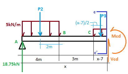
 For segment CD: [cutting plane b-b'] 40<x<50m


-60\left&space;(&space;x-15&space;\right&space;)-40\left&space;(&space;x-40&space;\right&space;)-M_{CD}=0 "50\left ( x \right )-60\left ( x-15 \right )-40\left ( x-40 \right )-M_{CD}=0")

 Shear and Moment Diagrams
The shear diagram follows the load. Reaction at point A goes upward and stays constant until point B. From point B an applied downward load of 60kN takes the shear diagram at -10kN. The -10kN stays constant until point C wherein an additional -40kN added, resulting to -50kN. The support reaction at point D takes the -50kN back to zero shear.
For the moment diagram, it is more convenient to use the equations:
For: , start at x=0, the moment at point A (x=0) is 0.
At x= 15m, the moment at point B (x=15m) is 750kN.m
For: ,
check by placing x=15 (at point B), the moment is 750kN.m so the value coincides with the first equation at the same point B.
At x=40m (at point C), the moment is 500 kN.m.
For: , check by placing x=40 (at point C), the moment is 500kN.m which coincides with the previous computation.
At x=50m, the moment results to 0.
RELATED TOPIC:
4.4. EQUATION METHOD OF SHEAR AND MOMENT IN BEAMS