Wednesday 31 October 2018

ELASTIC FUNDAMENTAL PERIOD OF STRUCTURES

Basically, every system has a set of frequencies in which it responds to vibrate when set in motion by some disturbance such as seismic or wind event. This response is based on the mass and stiffness of the system. The shortest form of frequency is more known as the natural frequency and it is just the inverse of the fundamental building period.

In seismic analysis and design, if a structure's frequency is close to the frequency of the earthquake, more energy is introduced in the structure. Shorter fundamental periods attract higher seismic vibrations.

The elastic fundamental period of structures, T, can be computed in two ways.

METHOD A: APPROXIMATE FUNDAMENTAL PERIOD

The most straightforward method for determining the building period involves using empirical formulas based on information from several instrumented buildings.


where: Ct for steel- moment-resisting frames =0.0853
           Ct for reinforced concrete moment-resisting frames and eccentrically braced frames  = 0.0731
            Ct for all other buildings = 0.0488
            Ct for structures with concrete or masonry shear walls =


hn = total height of the building from the support or base to the top in each direction.

  where the value of  shall not exceed 0.90.

METHOD B. PROPERLY SUBSTANTIATED ANALYSIS USING EIGENVALUE ANALYSIS AND RAYLEIGH'S METHOD

Fundamental period, T, may be calculated using the structural properties and deformational characteristics of the elements.


where: fi = any lateral force distributed approximately 


RELATED ARTICLES:

Design Base Shear
Solving for Total Seismic Design Load
How to Determine the Coefficient of Over Strength and Ductility Capacity, R

Identifying the Importance Factor, I
What do Seismic Zones mean?
Philippine Seismic Source Types
Near Source Factors and Seismic Coefficient
Soil Profile Types

SOIL PROFILE TYPES

Soil shall be classified into one of the categories shown in the code. With the soil profile type, the appropriate site-dependent design spectrum can be defined.

Site categorization schemes of the seismic codes use different descriptions of geological and geotechnical parameters to define the soil classes. The most commonly used parameter is the    which is the average shear wave velocity of the top 30m of the soil profile.This was introduced in post 1994 in US seismic codes (the 1994 and 1997 edicitons of NEHR and also the 2000 IBC) as the main categorization parameter.

                                        
where:

di  = thickness of layer i in meters
Vsi = shear wave velocity in layer i in m/s

Soil Penetration Test (SPT) is one of the procedures to determine the soil bearing capacity. This test is economical, used to identify surface information on land and offshore.  Standard penetration blow count   is used.

                                       
where:
di  = thickness of layer i in mm
ds = the total thickness of cohesionless soil layers in the top 30m
Ni  = the standard penetration resistance of soil layer from standards

And lastly, the undrained shear strength  may also be used to characterize the top 30m of the soil.


where: 
dc  = the total thickness of cohesive layers in the top 30m.
Sui = the undrained shear strength in the standards, not to exceed 250 kPa.

SOIL PROFILE TYPES


SOIL PROFILE TYPEGENERIC DESCRIPTIONSHEAR WAVE VELOCITY VS,30SPT, N (BLOWS/300mm) UNDRAINED SHEAR STRENGTH SU (kPa)
SaHard rock> 1500
SbRock760 to 1500
ScVery dense soil and soft rock360 to 760> 50> 100
SdStiff soil profile180 to 36015 to 5050 to 100
SeSoft soil profile< 180< 15< 50
Sf

NOTE:
  • Soil Profile Sf is noted as soil requiring site-specific evaluation.
  • Soil Profile Type Se also includes any soil profile with more than 3.0m of soft clay defined as a soil with plasticity index > 20, and Su<24kPa.
NSCP reserves the exception:

"When the soil properties are not known or with insufficient detail , Type Sd shall be used." Soil profile type Se or Sf need not be assumed unless the building official determines that type Se or Sf may be present at the site or in the event that type Se or Sf is established by geotechnical data."


RELATED ARTICLES:

Design Base Shear
Solving for Total Seismic Design Load
How to Determine the Coefficient of Over Strength and Ductility Capacity, R
Identifying the Importance Factor, I
What do Seismic Zones mean?
Philippine Seismic Source Types
Near Source Factors and Seismic Coefficient
Elastic Fundamental Period of Structures

NEAR SOURCE FACTORS AND SEISMIC COEFFICIENTS

Near source factors are used in determining base shear when analyzing lateral forces in designing structures. Na and Nv account for the proximity to the nearest active fault. Although the NSCP specified interpolation of factors depending on the location of the structure, most designers consider the lumped location of structures whether located in a near field or far field.


 = near source coefficient (velocity)

 = near source coefficient (acceleration)


NSCP 2015 introduced the less than 2km distance. Although still debatable, most designers work on using this range for their designs instead of interpolating the actual value for the structure in the maps provided.


NEAR-SOURCE FACTOR Na


SEISMIC SOURCE TYPECLOSEST DISTANCE TO KNOWN SEISMIC SOURCE
< = 2 km< = 5 km> = 10 km
A1.51.21.0
B1.31.01.0
C1.01.01.0

NEAR-SOURCE FACTOR Nv


SEISMIC SOURCE TYPECLOSEST DISTANCE TO KNOWN SEISMIC SOURCE
<= 2 km< = 5 km<= 10 km>= 15 km
A2.0 1.6 1.2 1.0
B1.6 1.2 1.0 1.0
C1.0 1.0 1.0 1.0


From those values taken from nearness factors, the parameters for seismic coefficients can thus be identified.


 = Seismic coefficient (acceleration)

 = Seismic coefficient (velocity)


SEISMIC COEFFICIENT, Cv


SOIL PROFILE TYPESeismic Zone, Z
Zone 2Zone 4
Sa0.160.32Nv
Sb0.200.40Nv
Sc0.320.56Nv
Sd0.400.64Nv
Se0.640.96Nv
SfNote 1

SEISMIC COEFFICIENT, Ca


SOIL PROFILE TYPESeismic Zone, Z
Zone 2Zone 4
Sa0.16 0.32Na
Sb0.20 0.40Na
Sc0.24 0.40Na
Sd0.28 0.44Na
Se0.34 0.44Na
SfNote 1

NOTE 1: 
Site-specific geotechnical investigation and dynamic site response analysis shall be performed to determine seismic coefficients.

RELATED ARTICLES:

Design Base Shear
Solving for Total Seismic Design Load
How to Determine the Coefficient of Over Strength and Ductility Capacity, R
Identifying the Importance Factor, I
What do Seismic Zones mean?
Philippine Seismic Source Types
Near Source Factors and Seismic Coefficients
Soil Profile Types
Elastic Fundamental Period of Structures

PHILIPPINE SEISMIC SOURCE TYPES

Having the Philippines situated in the the earthquake belt, most, if not all, parts of the country have experienced ground excitation one way or the other. The NSCP has stipulated three source descriptions of earthquakes from More than magnitude 7 to less than magnitude 6.5 which would most likely to occur in any region of the country. These values are used as they are the destructive range of magnitudes. It is left to the designer's prerogative on which to adopt.

In places where history does not reveal damaging seismic magnitudes, then the designer can opt to use the category showing less than magnitude 6.5. In most other places, designers keep the first line for factor of safety adopting the design for magnitudes more than 7.0.


SEISMIC SOURCE TYPESEISMIC SOURCE DESCRIPTIONMAXIMUM MOMENT MAGNITUDE, M
A"Faults that are capable of producing large magnitude
events and that have a high rate of seismic activity."M is greater than or equal to 7.0
BAll faults other than Types A and C."M is greater than or equal to 6.5
but less than 7.0"
C"Faults that are not capable of producing large magnitude
earthquakes and that have a relatively low rate of
seismic activity."M is less than 6.5


RELATED ARTICLES:

WHAT DO SEISMIC ZONES MEAN?

A seismic zone is a region in which there is a fairly consistent seismic activity. This means that the frequency and magnitude of seismic activities may be rare or may be extremely common. The term "seismic zone" is used to talk about an area with increase in seismic activities, whereby other people refer it as "seismic hazard zone" when discussing areas with more frequent seismic activities.

According to United States Geological Survey, USGS, seismic zoning numbered 0, 1, 2, 3, 4 are practically outdated. This designation had been used for the last time in 1969. The Uniform Building Code of 1997 is the only building code that still uses such zone. For the last past two decades, building codes have replaced maps with contours of design ground motion.

The Medvedev-Sponheuer-Karnik (MSK or MSK-64) is a macroseismic intensity scale for the evaluation of the severity of ground excitation using observed effects in the area of occurence. MSK intensity broadly associates the different seismic zones 2, 3, 4, 5 respective with seismic zones VI (or less), VII, VIII, and IX (and above) corresponding to Mazimum Considered Earthquake (MCE). Each of these zones indicates the effects of an earthquake at a particular place from observations on the affected areas. This can also be described using scales like Modified Mercalli or Medvedev-Sponheue-Karnik scale.


ZONESDEFINITION
5VERY HIGH RISK ZONE
Covers the areas with the highest risk zones that suffer earthquakes of intensity MSK IX or greater.
Structural designers use this factor for earthquake resistant design of structures.
The areas having trap rock or basaltic rock are prone to earthquakes of this zone.
4HIGH RISK ZONE / HIGH DAMAGE RISK ZONE
Covers areas liable to MSK VIII.
3MODERATE RISK ZONE / MODERATE DAMAGE RISK ZONE
Liable to MSK VII
2LOW RISK ZONE / LOW DAMAGE RISK ZONE
This region is liable to MSK VI (or less)

In the design of base shear, the seismic zone factor used for the two zones in the Philippines are:


ZONE 24
Z0.20.4
credits for iisee

RELATED ARTICLES:

Tuesday 30 October 2018

IDENTIFYING THE IMPORTANCE FACTOR, I

The ASCE Library defines importance factor as
" A function of the Risk Category, with the primary use of determination of design lateral forces. "
However, the true purpose of the importance factor is to provide an additional strength for risk-critical facilities. The more important facilities are to be designed with an increased value of the seismic design coefficients of the ordinary structures by a certain factor.

NSCP has categorized buildings into 5 groups:

1. CATEGORY I: ESSENTIAL FACILITIES

These are facilities or structures which are necessary to remain operational or could be restored quickly after struck by an earthquake for people to respond effectively.

These structures are necessary for emergency response and must not just survive a major earthquake, but should also be able to function at full efficiency even right after a disaster. These structures should be designed and located, constructed in a way that they can continue to function immediately after or during a major earthquake. 

Essential facilities consist the following:
  1. Emergency communications. Emergency operations centers must be able to detect and determine the most serious problems and respond by quickly dispatching response teams for rescue, fire fighting, medical care, etc.
  2. Hospitals. Hospitals in a region must operate at maximum capacity in times of major disasters. Any damage of the building or to equipment and supplies can impair medical response to an emergency.
  3. Emergency response facilities. Structures which should have the ability to provide immediate response during a disaster. Examples are ambulance services, police stations, emergency operation centers, and fire stations.
  4. Catastrophic failures. Structures which can worsen the situation during a disaster, such as failure of a large dam or a nuclear power plant.
  5. Transportation and communication. Collapsed buildings and downed electrical lines can block and bring serious damage to the transportation and communication networks. These networks are necessary for delivery of aid, doctors,rescue workers, food, etc.
  6. Utilities. Lifeline systems which provide, water, fuel, electricity, sewers and communication and transportation to the community.
  7. Designated evacuation centers. Structures housing evacuees after a disaster. This includes public school buildings which are always used as evacuation centers.
2. CATEGORY II. HAZARDOUS/CRITICAL FACILITIES

These facilities include all man-mad structures or their improvements which may pose potential threats or cause serious bodily harm, extensive damage to property, disruption of socioeconomic activities if damaged. 

Some of these structures, building or non-building, support or house toxic and explosive substances.

3. CATEGORY III. SPECIAL OCCUPANCY STRUCTURES

Structures with high population such as enumerated below:
  1. Structures for public assembly with capacity of more than 1,000 persons.
  2. Schools with 250-student capacity which are not categorized as evacuation centers. Also included are educational buildings such as libraries, museums, auditoriums with more than 300 occupants.
  3. Adult education schools like colleges with more than 500 students.
  4. Medical facilities such as mental hospitals.
  5. Detention facilities like jails.
  6. Churches, mosques, and religious facilities.
  7. Other structures and equipment in power-generating stations, and utility facilities not under category I.
4. CATEGORY IV. STANDARD OCCUPANCY STRUCTURES

Structures not having functions as stated previously. Residential housing falls under this category.

5. CATEGORY V. LOW-RISK STRUCTURES

Structures which exhibit low risk to human life and property in any event of failure. Examples are agricultural buildings, temporary facilities, boundary walls, minor storage facilities, construction facilities, private garages, carports, sheds, and fences.


OCCUPANCY CATEGORYSEISMIC IMPORTANCE FACTOR, I
I. Essential facilities1.50
II. Hazardous facilities1.25
III. Special Occupancy facilities1.00
IV. STandard Occupancy facilties1.00
V. Low Risk Structures1.00

RELATED ARTICLES:

HOW TO DETERMINE THE COEFFICIENT OF OVER STRENGTH AND DUCTILITY CAPACITY, R

The coefficient R in computing for base shear in static force method represents the inherent over-strength and global ductility capacity of lateral-force-resisting systems. 

There are 4 tables for this value (Table 208-11), categorized with the different materials used for the frames - for concrete, steel, masonry, and wood. Different tables contain the different seismic-force resisting system namely:

1. Bearing-wall systems. Structural systems where building loads (dead and live looads) are transferred to the ground through walls. 

2. Building frame systems. Structural systems with complete space frames to support vertical loads. 

Note: The value of R for building frame systems is greater than that assigned to bearing wall systems, thus the former is more desirable from a cost-efficient design perspective.

3. Moment-resisting frames. Rectilinear Structural assemblages of beams and columns with beams rigidly connected to the columns.

4. Dual systems. Structural systems where a complete frame provides support from gravity loads. Lateral loads support is provided by moment -resisting frame ad braced frames of shear walls.

5. Cantilevered column building frames. Seismic force-resisting systems whereby lateral loads are resisted by columns acting as vertical cantilevers.

6. Shear-wall frame interaction systems. Structural systems with combination of shear walls and frames to provide the required stiffness and strength in withstanding loads in high rise buildings.

NSCP uses moment-resisting frames, particularly special moment resisting frames. The other two kids of these kinds of frames are ordinary and intermediate.
  • Ordinary moment resisting frames do not meet special detailing requirements for ductile behavior.
  • Intermediate moment resisting frames are concrete or steel frames designed in accordance to section 8.3 in BNBC 93.
  • Special moment resisting frame is specially detailed to provide ductile behavior complying with seismic requirements provided in BNBC 93.
NSCP specifies using Special moment resisting frames for analysis and study on lateral loads.

TABLE 208-11A Earthquake-force-resisting Structural Systems of Concrete

BASIC SEISMIC-FORCE RESISTING SYSTEM R
A. BEARING WALL SYSTEMS
Special reinforced concrete shear walls4.5
Ordinary reinforced concrete shear walls4.5
B. BUILDING FRAME SYSTEMS
Special reinforced concrete shear walls or braced frames (shear walls)5
Ordinary reinforced concrete shear walls or braced frames 5.6
Intermediate precast shear walls or braced frames 5
C. MOMENT-RESISTING FRAME SYSTEMS
Special reinforced concrete moment frames8.5
Intermediate reinforced concrete moment frames5.5
Ordinary reinforced concrete moment frames3.5
D. DUAL SYSTEMS
Special reinforced concrete shear walls8.5
Ordinary reinforced concrete shear walls6.5
E. DUAL SYSTEM WITH INTERMEDIATE MOMENT FRAMES
Special reinforced concrete shear walls6.5
Ordinary reinforced concrete shear walls5.5
Shear wall frame interactive system with ordinary reinforced concrete
moment frames and ordinary reinforced concrete shear walls"4.2
F. CANTILEVERED COLUMN BUILDING SYSTEMS
Cantilevered column elements2.2
G. SHEAR WALL-FRAME INTERACTION SYSTEMS5.5

TABLE 208-11B Earthquake-force-resisting Structural Systems of Steel


BASIC SEISMIC-FORCE RESISTING SYSTEM R
A. BEARING WALL SYSTEMS
Light steel-framed bearing walls with tension-only bracing2.8
Braced frames where bracing carries gravity load4.4
Light framed walls sheathed with steel sheets structural panels rated for
shear resistance or steel sheets5.5
Light-framed walls with shear panels of all other light materials4.5
Light-framed wall systems using flat strap bracing2.8
B. BUILDING FRAME SYSTEMS
Steel eccentrically braced frames (EBF), moment resisting connections at
at columns away from links8.0
Steel eccentrically braced frames (EBF), non-moment-resisting connections
away from links6.0
Special concentrically braced frames (SCBF)6.0
Ordinary concentrically braced frames (OCBF)3.2
Light-framed walls sheathed with steel sheet structural panels/sheet steel
panels6.5
Light frame walls with shear panels of all other materials2.5
Buckling-restrained braced frames (BRBF), non-moment-resisting
beam-column connection"7.0
Buckling-restrained braced frames, moment-resisting beam-column connections8.0
Special steel plate shear walls (SPSW)7.0
C. MOMENT-RESISTING FRAME SYSTEMS
Special moment-resising frame (SMRF)8.0
Intermediate steel moment frames (IMF)4.5
Ordinary moment frames (OMF)3.5
Special truss moment frames (STMF)6.5
Special composite steel and concrete moment frames8.0
Intermediate composite moment frames5.0
Composite partially restrained moment frames6.0
Ordinary composite moment frames3.0
D. DUAL SYSTEMS WITH SPECIAL MOMENT FRAMES
Steel eccentrically braced frames8.0
Special steel concentrically braced frames7.0
Composite steel and concrete eccentrically braced frame8.0
Composite steel and concrete concentrically braced frame6.0
Composite steel plate shear walls7.5
Buckling-restrained braced frames (BRBF), non-moment-resisting
beam-column connection"8.0
Special steel plate shear walls8.0
Masonry shear wall with steel OMRF4.2
Steel EBF with steel SMRF8.5
Steel EBF with steel OMRF4.2
Special concentrically braced frames with steel SMRF7.5
Special concentrically braced frames with steel OMRF4.2
E. SUAL SYSTEM WITH INTERMEDIATE MOMENT FRAMES
Special steel concentrically braced frame6.0
Composite steel and concrete concentrically braced frame5.5
Ordinary composite braced frame3.5
Ordinary composite reinforced concrete shear walls with steel elements5.0
F. CANTILEVERED COLUMN BUILDING SYSTEMS
Special steel moment frames2.2
Intermediate steel moment frames 1.2
Ordinary steel moment frames1.0
Cantilevered column elements2.2
G. STEEL SYSTEMS NOT SPECIFICALLY DETAILED FOR SEISMIC RESISTANCE,
EXCLUDING CANTILEVER SYSTEMS3.0


TABLE 208-11C Earthquake-force-resisting Structural Systems of Masonry


BASIC SEISMIC-FORCE RESISTING SYSTEM R
A. BEARING WALL SYSTEMS
Masonry shear walls4.5
B. BUILDING FRAME SYSTEMS
Masonry shear walls5.5
C. MOMENT-RESISTING FRAME SYSTEMS
Masonry moment-resisting wall frames (MMRWF)6.5
D. DUAL SYSTEMS
Masonry shear walls with SMRF5.5
Masonry shear walls with OMRF4.2
Masonry shear walls with concrete IMRF4.2
Masonry shear walls with masonry MMRWF6.0

TABLE 208-11D Earthquake-force-resisting Structural Systems of Wood


BASIC SEISMIC-FORCE RESISTING SYSTEM R
A. BEARING WALL SYSTEMS
Light-framed walls with shear panels: wood structural panel walls for structures
three stories or less5.5
Heavy timber braced frames where bracing carries gravity load2.8
All other light framed wallsNA
B. BUILDING FRAME SYSTEMS
Ordinary heavy timber-braced frames5.6

RELATED ARTICLES:

Monday 29 October 2018

SOLVING FOR TOTAL SEISMIC DESIGN LOAD

The different procedures for solving base shear all contain total seismic design load, W. Although this is mainly the dead load computed from the structural configuration, there are cases where W is a combination of loads.

Warehouses and stores consider a combination of dead load of the building and 25% of the live load. This is due to inventory placed and stacked in the structure.


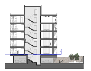
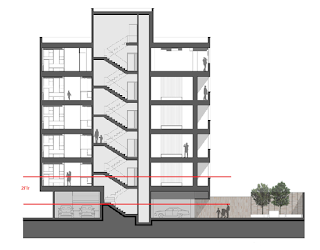
Total seismic design load only considers the members on top of the gradeline. In cases where another support is placed above the gradeline, the total seismic design load would change and adopt to the level on top of the support.
credits from ArchDaily


Unit weight of construction materials are considered in computing the dead load (204-1).


  • Reinforced concrete, stone, including gravel   =      
  • Exterior and partition walls are measured in   or kPa. Note that values in the table are given for unplastered  walls, thus additional 0.24 kPa for each phase if plastered. Computation for the weight of masonry walls would have to multiply the tributary height by the unit weight.
                    

Dead Loads adopted in the Philippines:


MATERIALDRY UNIT WEIGHT
Structural Steel76.8 kN/cu.m (490pcf)
Reinforced concrete23.54 kN/cu.m (150pcf)
Slab per 10mm thk2.35 kPa (50.0psf)
Floor finish and toppings1.20 kPa (12.5psf)
Ceilings and utilities0.24 kPa (5.0psf)
Exterior wall (150mm thk CHB)2.80 kPa (57.0psf)
Interior Partitions (100mm thk CHB)2.00 kPa (42.0psf)
Waterproofing/topping1.20 kPa (12.5psf)
Movable partition1.00 kPa (20.0psf)


PROCEDURE ON COMPUTING DEAD LOADS

1. Take the volume of slabs and beams and multiply with the unit weight.

2. The weight of the columns and walls are computed using the tributary height. The weight of columns (and walls) for the second floor considers the weight of the columns using the lower half (half of the first floor) and the upper half (half of the second floor).

3. Take the summation of loads per floor.

RELATED ARTICLES:

Design of base shear
How to Determine the Coefficient of Over Strength and Ductility Capacity, R
Identifying the Importance Factor, I
What do Seismic Zones mean?
Philippine Seismic Source Types
Near Source Factors and Seismic Coefficient
Soil Profile Types
Elastic Fundamental Period of Structures

DESIGN BASE SHEAR

The earthquake design of any structure starts with the design base shear. This shear is an estimate of the expected maximum force which occurs laterally to the ground where the structure stands.

Base shear, V, depends on the following parameters:


  1. Site soil conditions
  2. Proximity to faults or sources of seismic activity.
  3. Seismic ground motion probability
  4. Structural configurations, its level of ductility and strength
  5. Total weight of the structure
  6. Structure's fundamental period of vibration when under dynamic loading

1. Simplified Static Force Procedure


2. Static Force Procedure

The total design base shear  shall be computed as follows:


This design base shear will govern under the following conditions:

  • The computed base shear shall not exceed:
                                  

  • The computed base shear shall not be less than:
                                  

  • Also, the computed base shear shall not be less than the following if structure is located in Seismic Zone 4
                                 

where:

 = total design base shear
W = total seismic dead load (208.5.2.1)
I   = Importance factor (208-1)
R  = coefficient for the inherent over-strength and global ductility capacity of lateral-force-resisting systems (208-11 or 208-12)
 and = seismic coefficient (208-7 and 208.8)
Z    = seismic zone factor (208-3)
 = near source factor for  (208-4 and 208-6)

PROCEDURES FOR SEISMIC DESIGN FORCE

Equivalent Lateral Force (ELF) has been widely used due to both simplicity and efficiency. The National Structural Code of the Philippines (NSCP) uses ELF in the design of structures.

Under this method, three categories are followed referring to the structure configuration (208.4.8)


1. Simplified Static

Simplified static procedure is used for structures under Occupancy Categories IV and V. (208.4.8.1)
  • Category IV.  Standard Occupancy Structures. All structures for housing occupancies  or having other functions not listed in Categories I, II, III, or V.
  • Category V. Private garages, carports, sheds and fences of height over 1.5m.

2. Static

This procedure is used for the following structure configuration (208.4.8.2):

  1. Structures, regular or irregular, located under Seismic Zone 2 and under Occupancy Categories IV and V.
  2. Regular structures under Occupancy Categories I, II, III, rising under 75m and with specified force resisting frame systems.
  3. Irregular structures NOT more than 20 meters (approx 5 stories) in height.
  4. Structures with flexible upper portion but rigid lower portion.

3. Dynamic

The dynamic procedure of lateral force method is used for all other structures not falling under any between simplified static and static procedures (208.4.8.3).
  1. Regular structures which are high rise, that is, more than 75m in height.
  2. Structures having irregularity on stiffness, weight or geometric vertical configuration.
  3. Irregular structures over 20 meters in height (five stories), or located in Seismic Zone 4.
  4. Regular or irregular structures located on Soil Profile 
  5. , which carries a period greater than 0.70s.

EARTHQUAKE ANALYSIS

Unlike other disasters, the advance technology currently available still fall short in predicting the occurrence and magnitude of earthquakes. In designing buildings subject to earthquakes, it is still advisable to keep a conservative factor of safety. There are three types of analysis used currently:

1. Response History Analysis

This type of analysis considers the response of a building as a function of time. The time span considered is that period when the structure is subjected to a specific ground acceleration.

Using Newton's Second Law of Motion, stating that a body will move in a certain acceleration which is inversely proportional to its mass but directly proportional to the force if motion is present, that is, resultant force acting on it is non zero.

Forces on the body is identified as a function of time


2. Response Spectrum Analysis

RSA is another statistical analysis which is linear-dynamic by nature. It measures the vibration to show the most feasible maximum seismic response of an elastic structure. This uses pseudo-spectral acceleration where velocity and displacement are functions of a specific period in a span of a certain time history and also with level of damping.

RSA is useful when analyzing dynamic performance. Structures experience greater vibrations of ground acceleration with shorter period. On the other hand, with longer period, structures go thought greater displacement.

3. Equivalent Lateral Forces

ELF is a conservative method utilizing static analysis method. However, it requires data from dynamic analysis - mass. Similar with the previous analyses, Newton's Second Law of Motion is still used in deriving the formula specifically:


Tuesday 23 October 2018

6.0. PIPES

Energy losses from various sources reduce flow discharge when a fluid moves through a pipeline. A boundary layer is formed on the pipe walls which causes continuous resistance. Velocity decreases from the center of the pipe to zero (at the boundary)in the boundary layer. 


The total head loss along a specified length of pipeline is commonly referred to as the "head loss due to friction", which is denoted by . The rate of energy loss or energy gradient  .


Click here for pdf notes on Pipes


Click here for pdf copy of PROBLEM SET (HYDRAULICS) [reference: Hydraulics by King, Wisler, Woodburn]

Click here for pdf copy of HOMEWORK (HYDRAULICS)


Applying Bernoulli's equation to two sections on a pipe, 


head loss is categorized into two.


  1. Major head loss (due to friction)
  2. Minor head loss (local losses)

6.1. HEAD LOSS DUE TO FRICTION


Head loss due to friction is considered a major head loss which is continuous. It is assumed to occur at a uniform rate along the pipe when the size and quality are constant. 

There are different formulas used to determine the frictional loss.

6.1.1. DARCY WEISBACH FORMULA


A commonly used formula for pipes, Dary Weisbach's formula expresses the head in terms of velocity head.


where:  f=  friction factor
            L=  length of pipe
            D= diameter of pipe
            V= velocity of fluid flow
            = head loss due to friction

If discharge is considered instead of velocity head.


So


                    [SI units]


6.1.2. F VALUES FOR WATER

The friction factor, f, is a dimensionless coefficient which depends on the velocity of flow, diameter of pips, and density and viscosity of fluid.  Fanning's equation identified that friction factor is a function of the Reynold's number and the relative roughness of the pipe material. With the variation of friction factor characteristics with laminar and turbulent flows, the Hagen-Poiseuille equation is used to determine the Fanning equation:

                                [for laminar flow: Re<2100]

                    [for turbulent flow: Re>2100]


The Fannings table below represents friction factor for laminar flow in new cast iron pipes, welded steel pipes, wood pipes made of planed staves, concrete pressure pipes, and cement-lined steel pipes.


Pipe diaMean Velocity(V) in Feet per Second
(in)0.50 1.00 2.00 3.00 4.00 5.00 10.00 15.00 20.00
0.50.042 0.038 0.034 0.032 0.030 0.029 0.025 0.024 0.023
0.750.041 0.037 0.033 0.031 0.029 0.028 0.025 0.024 0.023
10.040 0.035 0.032 0.030 0.028 0.027 0.024 0.023 0.023
1.50.038 0.034 0.031 0.029 0.028 0.027 0.024 0.023 0.023
20.036 0.033 0.030 0.028 0.027 0.026 0.024 0.023 0.022
30.035 0.032 0.029 0.027 0.026 0.025 0.023 0.022 0.022
40.034 0.031 0.028 0.026 0.026 0.025 0.023 0.022 0.021
50.033 0.030 0.027 0.026 0.025 0.024 0.022 0.022 0.021
60.032 0.029 0.026 0.025 0.024 0.024 0.022 0.021 0.021
80.030 0.028 0.025 0.024 0.023 0.023 0.021 0.021 0.020
100.028 0.026 0.024 0.023 0.022 0.022 0.021 0.020 0.020
120.027 0.025 0.023 0.022 0.022 0.021 0.020 0.020 0.019
140.026 0.024 0.022 0.022 0.021 0.021 0.020 0.019 0.019
160.024 0.023 0.022 0.021 0.020 0.020 0.019 0.019 0.018
180.024 0.022 0.021 0.020 0.020 0.020 0.019 0.018 0.018
200.023 0.022 0.020 0.020 0.019 0.019 0.018 0.018 0.018
240.021 0.020 0.019 0.019 0.018 0.018 0.018 0.017 0.017
300.019 0.019 0.018 0.018 0.017 0.017 0.017 0.016 0.016
360.018 0.017 0.017 0.016 0.016 0.016 0.016 0.015 0.015
420.016 0.016 0.016 0.015 0.015 0.015 0.015 0.015 0.014
480.015 0.015 0.015 0.015 0.014 0.014 0.014 0.014 0.014
540.014 0.014 0.014 0.014 0.014 0.014 0.013 0.013 0.013
600.014 0.013 0.013 0.013 0.013 0.013 0.013 0.013 0.012
720.013 0.012 0.012 0.012 0.012 0.012 0.012 0.012 0.012
840.012 0.012 0.011 0.011 0.011 0.011 0.011 0.011 0.011


RELATED TOPICS:


6.2. GENERAL METHOD OF DETERMINING DARCY WEISBACH'S FRICTION FACTOR- THE MOODY DIAGRAM

6.3  CONVERTING HEAD INTO PRESSURE

6.4. THE HYDRAULIC RADIUS
6.5. OTHER PIPE FORMULAS

6.6. MINOR LOSSES

6.7. PIPES AND RESERVOIRS

6.8. PIPES IN SERIES

6.9. PIPES WITH BRANCHES IN PARALLEL

6.10. THE THREE RESERVOIR PROBLEM