So reinforcing bars are vital components of a concrete structure. One requirement before the construction kicks in is to submit a detailed list of reinforcement. There are structural parts whereby it is easy to determine the number of rebars needed or its equivalent weight; however, there are many members requiring direct count method - which is more tedious but better detailed.
The main structural members where detailed estimates of reinforcement is required are:
1. Footings
2. Columns and posts
3. Beams and girders
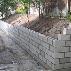
4. CHB walls
5. Slab - one way and two way
| DIAMETER | 5.0m | 6.0m | 7.5m | 9.0m | 10.5m | 12.0m | 13.5m |
|---|
|
kg
|
kg
|
kg
|
kg
|
kg
|
kg
|
kg
|
|
|
|
|
|
|
|
|
8mm
|
1.98
|
2.37
|
2.96
|
3.56
|
4.15
|
4.74
|
5.33
|
10mm
|
3.08
|
3.7
|
4.62
|
5.544
|
6.47
|
7.39
|
8.32
|
12mm
|
4.44
|
5.33
|
6.66
|
7.992
|
9.32
|
10.66
|
11.99
|
13mm
|
5.21
|
6.25
|
7.83
|
9.38
|
10.94
|
12.5
|
14.07
|
16mm
|
7.9
|
9.47
|
11.84
|
14.21
|
16.58
|
18.95
|
21.32
|
20mm
|
12.33
|
14.8
|
18.5
|
22.19
|
25.89
|
29.59
|
33.29
|
25mm
|
19.27
|
23.12
|
28.9
|
34.68
|
40.46
|
46.24
|
52.02
|
28mm
|
24.17
|
29
|
36.25
|
43.5
|
50.75
|
58
|
65.25
|
30mm
|
27.75
|
33.29
|
41.62
|
49.94
|
58.26
|
66.59
|
74.91
|
32mm
|
31.57
|
37.88
|
47.35
|
56.82
|
66.29
|
75.76
|
85.23
|
36mm
|
39.96
|
47.95
|
59.93
|
71.92
|
83.91
|
95.89
|
107.88
|
7.2. BAR SPLICE, HOOK AND BEND
a. SPLICE LENGTH:
In steelwork estimating, splicing, hooks, and bends should be accounted for.
+150mm)
 Example 7.2.1. Determining Splice Lengths
Example 7.2.1. Determining Splice Lengths
b. HOOK LENGTH
Hooks are often placed with lateral ties or stirrups to hold the shape of the ties. Usually, hook length (for one side) is nine times the diameter of the rebar.

c. BEND LENGTH
Bends are often placed with bigger diameter bars as it is hard to make hooks on them. Bends are considered to anchor a member to another, such as column to a footing. Bend length is considered as sixteen times the bar diameter. In other cases, bends are taken from plans' specifications.
 d. DEVELOPMENT LENGTH
This length is required of the bar to transfer the stress it is carrying into the concrete. Most often development length is computed as:

7.3. REINFORCEMENT REQUIREMENTS OF STRUCTURAL MEMBERS
There are parts of reinforcement that an estimator should be familiar with:
a. CHB WALLS
- Vertical reinforcement
- Horizontal reinforcement
b. FOOTING REINFORCEMENTS
- Footing slab reinforcement for small and medium size
- Beam reinforcement for large foundations
- Dowels
c. POST AND COLUMN REINFORCEMENTS
- Main vertical reinforcement
- Lateral ties
1. Outer ties
2. Inner ties
3. Straight ties
d. BEAM AND GIRDER REINFORCEMENTS
2. Bend bars
2. Closed stirrups
1. Over and across the support
2. Between supports
3. Dowels
e. FLOOR SLAB REINFORCEMENT
1. Straight main reinforcing bars
2. Main alternate reinforcing bend bars
- Temperature bars
- Cut additional alternate bars over support (beam)
- Dowels
7.4. PROCEDURE OF ESTIMATING CONCRETE REINFORCEMENT
- Columns, beams, girders, and the like are best determined using direct counting.
- For lateral ties, stirrups, spirals, dowels, cut bars, and the like, estimation should be done one at a time. The length of bars should include the additional length of bends and hooks.
- After determining the length of lateral ties, stirrups and the similar reinforcements, select the commercial size yielding the least wastage.
- Tie wire for reinforcement joints and intersections should be done to the minimum required length based from the diameter of the bars to be tied with.
7.5. REINFORCEMENT OF CHB WALLS
Specifications for the reinforcement of CHB walls are usually written on the plan and specifications. The different ways to estimate them are as follows:
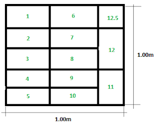
- By direct counting method. Vertical and horizontal wall reinforcements are directly counted from the plans. Length includes hooks, bends or splices.
- By the unit block method.
- By the area method. Estimation of wall reinforcements with the help of a table. The presented values include allowances for bends, hooks and splices.
VERTICAL REINFORCEMENT
| SPACING | LENGTH OF BARS | LENGTH OF BARS |
|---|
| PER BLOCK | PER SQ.M. |
| cm. | m. | m. |
| | |
| 40 | 0.235 | 2.930 |
| 60 | 0.171 | 2.130 |
| 80 | 0.128 | 1.600 |
HORIZONTAL REINFORCEMENT
| SPACING | LENGTH OF BARS | LENGTH OF BARS |
|---|
| LAYERS | PER BLOCK | PER SQ.M. |
| m. | m. |
| | |
| 2 | 0.264 | 3.30 |
| 3 | 0.172 | 2.15 |
| 4 | 0.138 | 1.72 |
7.6. TIE WIRE FOR STEEL REINFORCEMENT
No. 16 galvanized iron wire (#16 GI Tie Wire) is used to secure reinforcements in place for concrete pouring. Ordering tie wire does not come per length but per kilograms or roll. One roll is 45 kilograms which can be converted to 2285 meters. Thus making 53 meters per kilogram.
The length of each tie wire ranges from 20 cm to 40 cm for small and medium size steel bars. For 10mm, 12mm, 13mm, or 16mm rebars, tie wire length should be 25cm or 30cm (max), folded at the center.
KILOGRAM PER NUMBER OF CHB
| VERTICAL | HORIZONTAL | TIES | TIES |
|---|
SPACING
|
SPACING
|
25cm
|
30cm
|
cm
|
layer
|
kg
|
kg
|
|
|
|
|
40
|
2
|
0.0042
|
0.0051
|
40
|
3
|
0.0031
|
0.0038
|
40
|
4
|
0.0028
|
0.0033
|
60
|
2
|
0.0028
|
0.0034
|
60
|
3
|
0.0021
|
0.0025
|
60
|
4
|
0.0018
|
0.0022
|
80
|
2
|
0.0021
|
0.0025
|
80
|
3
|
0.0016
|
0.0019
|
80
|
4
|
0.0014
|
0.0017
|
7.7. INDEPENDENT FOOTING REINFORCEMENT
Procedure for estimating footing reinforcement is as follows:
- Know the actual size of the footing - it's width and length.
- Identify the bar size and the number from the plans.
- Always keep in mind that clear cover of reinforcements, when exposed to soil, is 3 inches or 75mm.
- If the pan does not call for a hook or bend of the reinforcement, the length of the bar is equal to the length of the width less the concrete cover at both ends.
- If not specified in the plans, better to identify the spacing of bars in the footing to determine the exact number of bars needed.
Example7.7.1. Estimating Isolated Footing Reinforcement
Example 7.7.2. Estimating Isolated Footing Reinforcement of a Small Structure
7.8. POST AND COLUMN REINFORCEMENT
Estimates of posts and columns include:
- The main or vertical reinforcement
- Lateral ties
- Spiral ties or circular column ties
MAIN REINFORCEMENT:
Estimate the main reinforcement of columns using the direct count method with the following lengths to note:
- Floor to floor height. Most plans show height of floors based on floor to floor distances. If otherwise specified, then add the thickness of the beam included.
- Depth of footing from the ground floor. Column height is usually measured from the bottom of the footing to the ground floor.
- Development length of column to footing. Development length is usually 10 times the bar diameter of the column.
- End splices. Splicing of reinforcement should be done in staggered mode - meaning, the lengths of bars used should not be the same. The ideal distribution is 33% but bar scheduling using 33% will be difficult. Most designers use 50%. Splicing points should be locations of minimal moment, that is, the last quarter of a span.
LATERAL TIES:
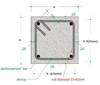
For the length of the ties, determine the concrete cover used. For columns, concrete cover ranges from 25mm to 40mm. Most designers use 25mm. Hooks for ties are taken as 2 inches each end.
The length of lateral ties can be computed as:
 |
| credits to Engineering Feed |
![Length_{lat ties}=2\left [ B-2\left ( 25mm \right ) \right ]+2\left [ D-2\left ( 25mm \right ) \right ]+2\left ( 50mm \right )](https://latex.codecogs.com/gif.latex?Length_{lat&space;ties}=2\left&space;[&space;B-2\left&space;(&space;25mm&space;\right&space;)&space;\right&space;]+2\left&space;[&space;D-2\left&space;(&space;25mm&space;\right&space;)&space;\right&space;]+2\left&space;(&space;50mm&space;\right&space;))
The number of lateral ties required is estimated by direct count.
Example 7.8.1. Estimating Column Reinforcement (Low-rise)
Example 7.8.2. Estimating Column Reinforcement (High-rise)
Example 7.8.3. Estimating Multiple Lateral Ties
7.9. BEAMS AND GIRDERS REINFORCEMENT
Estimating the reinforcement for beams and girders is similar but a bit more complicated with estimating columns.
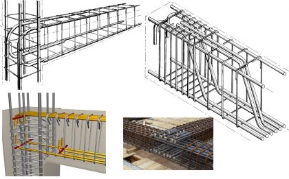
The main reinforcements are estimated similarly as with columns. But beams can have cut bars, which makes the difference. As per design, there could be different configurations between the top bars with the bottom bars in beams. Splicing is of beam reinforcement is located on the compression side.
 |
| credits to Orazio.it |
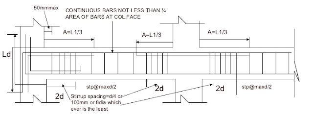
Extra bars can be cut or bent. Any of these are done based on economic reasons. The lengths of cut bars is based on the tension-compression functionality of the bar.
 |
| credits to Reinforcement Detailing |
Example 7.9.1. Estimating a simple Beam Reinforcement
Example 7.9.2. Estimating a Continuous Beam Reinforcement
Example 7.9.3. Estimating a Continuous Beam Reinforcement-II
7.10. SPIRAL AND COLUMN TIES
There are three considerations in the installation of spirals:
- The center to center spacing of the spiral should not exceed 1/6 of the diameter core.
- The clear spacing between spirals is within the range 5.0cm to 7.5cm.
- The clear spacing between spirals should be less than 1.5 times of the gravel.
NUMBER OF SPIRAL REINFORCING BARS PER METER HEIGHT
*Values given includes the end lap or splice allowance.
| COLUMN | PITCH | NO. OF TURN | NUMBER | OF STEEL | BARS FROM |
|---|
| DIAMETER | | PER METER HT | | | |
| cm | cm | | 6.00m. | 9.00m. | 12.00m. |
| | | | | |
| 30.0 | 5.00 | 21.0 | 2.604 | 1.706 | 1.269 |
| 30.0 | 6.25 | 17.0 | 2.108 | 1.381 | 1.027 |
| 30.0 | 7.50 | 14.3 | 1.778 | 1.165 | 0.866 |
| | | | | |
| 32.5 | 5.00 | 21.0 | 2.894 | 1.896 | 1.410 |
| 32.5 | 6.25 | 17.0 | 2.342 | 1.535 | 1.141 |
| 32.5 | 7.50 | 14.3 | 1.975 | 1.294 | 0.962 |
| | | | | |
| 35.0 | 5.00 | 21.0 | 3.183 | 2.085 | 1.55 |
| 35.0 | 6.25 | 17.0 | 2.577 | 1.688 | 1.255 |
| 35.0 | 7.50 | 14.3 | 2.172 | 1.423 | 1.058 |
| | | | | |
| 37.5 | 5.00 | 21.0 | 3.472 | 2.275 | 1.692 |
| 37.5 | 6.25 | 17.0 | 2.811 | 1.842 | 1.393 |
| 37.5 | 7.50 | 14.3 | 2.370 | 1.524 | 1.154 |
| | | | | |
| 40.0 | 5.00 | 21.0 | 3.762 | 2.465 | 1.833 |
| 40.0 | 6.25 | 17.0 | 3.045 | 1.995 | 1.484 |
| 40.0 | 7.50 | 14.3 | 2.567 | 1.682 | 1.251 |
| | | | | |
| 42.5 | 5.00 | 21.0 | 4.051 | 2.654 | 1.974 |
| 42.5 | 6.25 | 17.0 | 3.281 | 2.149 | 1.598 |
| 42.5 | 7.50 | 14.3 | 2.765 | 1.812 | 1.347 |
| | | | | |
| 45.0 | 5.00 | 21.0 | 4.340 | 2.844 | 2.115 |
| 45.0 | 6.25 | 17.0 | 3.513 | 2.302 | 1.712 |
| 45.0 | 7.50 | 14.3 | 2.962 | 1.940 | 1.443 |
| | | | | |
| 47.5 | 5.00 | 21.0 | 4.630 | 3.033 | 2.256 |
| 47.5 | 6.25 | 17.0 | 3.748 | 2.455 | 1.826 |
| 47.5 | 7.50 | 14.3 | 3.159 | 2.070 | 1.539 |
| | | | | |
| 50.0 | 5.00 | 21.0 | 4.919 | 3.223 | 2.397 |
| 50.0 | 6.25 | 17.0 | 3.982 | 2.609 | 1.940 |
| 50.0 | 7.50 | 14.3 | 3.357 | 2.199 | 1.635 |
| | | | | |
| 55.0 | 5.00 | 21.0 | 5.498 | 3.602 | 2.678 |
| 55.0 | 6.25 | 17.0 | 4.451 | 2.916 | 2.168 |
| 55.0 | 7.50 | 14.3 | 3.752 | 2.458 | 1.828 |
| | | | | |
| 60.0 | 5.00 | 21.0 | 6.077 | 3.981 | 2.96 |
| 60.0 | 6.25 | 17.0 | 4.919 | 3.223 | 2.396 |
| 60.0 | 7.50 | 14.3 | 4.146 | 2.717 | 2.02 |
| | | | | |
| 70.0 | 5.00 | 21.0 | 7.234 | 4.740 | 3.524 |
| 70.0 | 6.25 | 17.0 | 5.856 | 3.837 | 2.853 |
| 70.0 | 7.50 | 14.3 | 4.936 | 3.234 | 2.405 |
| | | | | |
| 80.0 | 5.00 | 21.0 | 8.391 | 5.498 | 4.088 |
| 80.0 | 6.25 | 17.0 | 6.793 | 4.451 | 3.31 |
| 80.0 | 7.50 | 14.3 | 5.726 | 3.752 | 2.790 |
| | | | | |
| 90.0 | 5.00 | 21.0 | 9.549 | 6.256 | 4.652 |
| 90.0 | 6.25 | 17.0 | 7.730 | 5.064 | 3.766 |
| 90.0 | 7.50 | 14.3 | 6.366 | 4.171 | 3.101 |
| | | | | |
| 100.0 | 5.00 | 21.0 | 10.706 | 7.014 | 5.216 |
| 100.0 | 6.25 | 17.0 | 8.667 | 5.678 | 4.222 |
| 100.0 | 7.50 | 14.3 | 7.137 | 4.676 | 3.477 |
Example 7.10.1. Estimate the spiral Reinforcement
7.11. REINFORCEMENT FOR ONE WAY CONCRETE SLAB
A slab will be designed as one-way when one side is less than half the other.
For one way slab, the only functional beams carrying the load are the long span. In this case side B. With the moment imposed on the long span beams, main reinforcement will also be along this span. The rebars placed along the shorter span is only to avoid shrinking of concrete or to avoid cracks. These bars are called temperature bars (distribution bars, straight bars).
Similar to the configuration of a beam, the main reinforcement will be placed in tension areas. That is, the upper portion of the slab on both ends, and the bottom portion in the middle part.
TABLE FOR AREA METHOD: ONE WAY SLAB
| BAR SPACING | NUMBER | OF STEEL | BARS PER | SQUARE | METER | TIE WIRE | LENGTH |
|---|
| 5.0m | 6.0m | 7.50m | 9.0m | 12.0m | 25cm | 30cm |
| | | | | | | |
| 10.0 | 4.493 | 3.667 | 2.856 | 2.320 | 1.834 | 0.242 | 0.291 |
| 12.5 | 3.911 | 3.186 | 2.483 | 2.015 | 1.593 | 0.197 | 0.236 |
| 15.0 | 3.524 | 2.866 | 2.234 | 1.812 | 1.433 | 0.163 | 0.195 |
| 17.5 | 3.247 | 2.637 | 2.056 | 1.667 | 1.319 | 0.141 | 0.169 |
| 20.0 | 3.039 | 2.465 | 1.192 | 1.558 | 1.233 | 0.126 | 0.152 |
| 22.5 | 2.878 | 2.332 | 1.819 | 1.473 | 1.166 | 0.111 | 0.133 |
| 25.0 | 2.749 | 2.225 | 1.737 | 1.405 | 1.113 | 0.101 | 0.121 |
| 27.5 | 2.643 | 2.138 | 1.669 | 1.350 | 1.069 | 0.091 | 0.109 |
| 30.0 | 2.554 | 2.065 | 1.612 | 1.304 | 1.033 | 0.086 | 0.103 |
Example 7.11.1. Estimating A One-Way Slab Reinforcement
7.12. REINFORCEMENT OF TWO-WAY SLAB
For two-way slab, all the surrounding beams carry load and are to be designed with main reinforcement. The temperature bars are placed under the slab on the sides of the slab with a quarter of the length. Estimation of bars is similar with one way slab main reinforcement.
TABLE FOR AREA METHOD: TWO-WAY SLAB
| BAR SPACING | NUMBER | OF STEEL | BARS PER | SQUARE | METER | TIE WIRE | LENGTH |
|---|
|
5.0m
|
6.0m
|
7.50m
|
9.0m
|
12.0m
|
25cm
|
30cm
|
cm
|
|
|
|
|
|
kg
|
kg
|
|
|
|
|
|
|
|
|
10.0
|
4.953
|
3.995
|
3.05
|
3.047
|
2.000
|
0.364
|
0.437
|
12.5
|
4.409
|
3.549
|
2.703
|
2.734
|
1.775
|
0.279
|
0.335
|
15.0
|
4.047
|
3.252
|
2.471
|
2.524
|
1.626
|
0.238
|
0.286
|
17.5
|
3.788
|
3.039
|
2.306
|
2.377
|
1.520
|
0.208
|
0.25
|
20.0
|
3.594
|
2.88
|
2.182
|
2.266
|
1.440
|
0.185
|
0.222
|
22.5
|
3.443
|
2.756
|
2.085
|
2.179
|
1.378
|
0.168
|
0.202
|
25.0
|
3.322
|
2.656
|
2.008
|
2.109
|
1.328
|
0.156
|
0.187
|
27.5
|
3.223
|
2.575
|
1.945
|
2.053
|
1.288
|
0.146
|
0.175
|
30.0
|
3.141
|
2.507
|
1.892
|
2.005
|
1.254
|
0.138
|
0.165
|
Example 7.12.1. Estimating Reinforcement of Two-way Slab
7.13. CONCRETE PIPE REINFORCEMENT
Concrete pipes also need longitudinal reinforcement and hoops.
Example 7.13.1. Estimating Reinforcement of a Concrete Pipe
